

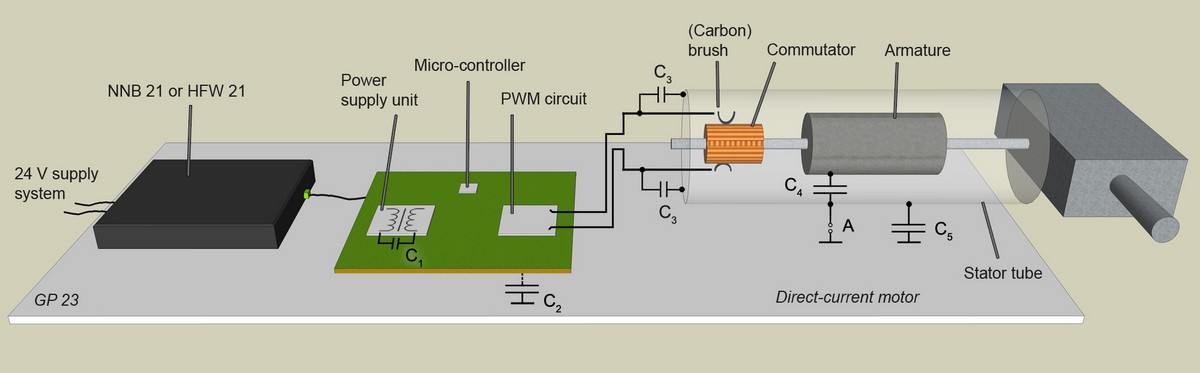
The equipment under test comprises a circuit board with a power supply unit, micro-controller, PWM and a direct-current motor.
The direct-current motor is connected to the circuit board's PWM output. The direct-current motor usually comprises an armature, a stator tube and a commutator with carbon brushes.
There are three distinctive emission sources:
- Power supply unit (interference suppression is difficult if the power supply unit is galvanically isolated)
- PWM circuit
- Switching operations of the commutator in connection with the armature inductance of the direct-current motor.
A line impedance stabilization network can be used to measure the emissions at the power supply input of the circuit board. Interference suppression is a complex task because the three emission sources overlap. It is usually rather difficult to trace the emissions back to their source on the basis of a spectrum.
In addition, there is a resonance between the PWM signal and the armature inductance that is produced by commutation if the direct-current motor is controlled by PWM.
This resonance significantly increases the emissions.
Operating the motor in the direct-current mode makes things easier.
It is helpful to suppress interference in each of the three emission sources separately. And it is best to start with the power supply unit.
A load resistor is used instead of the direct-current motor. The direct-current motor can be integrated into the test set-up as a passive component and is only connected via the anti-interference capacitors C3 (Figure 1). The PWM is switched off in this case.
Galvanically isolated power supply units generate a very high capacitive current that flows through the switching power-supply transformer. This current can be reduced through the du/dt limitation of the switching and kickback voltage. However, this is usually not sufficient. This current can be fed back to the source side if a capacitor C1 (Figure 1) is inserted.
The effect of the measures taken is measured and documented with the NNB 21 line impedance stabilization network or HFW 21 RF current transformer and the ChipScan-ESA software. The spectra that belong together can be coloured and superimposed by the software and can thus be compared quickly and easily.
Interference suppression in the PWM circuit is usually more complicated since the anti-interference capacitors C3 that are required to extinguish the sparking lead the PWM signal to the stator tube and from there to the ground reference plane (GP 23) of the measurement set-up. The current returns via the NNB 21 and is measured there as a noise current. The path it takes from the stator tube to the GP 23 can be via a fixed ground connection (A) or a parasitic capacitance C5 (Figure 1). The capacitors C3 should be small (around 1 nF) for the PWM mode of operation to keep the draining PWM noise current within certain limits. However, this is often not sufficient. Linear chokes that further reduce the PWM noise current have then to be inserted into the PWM line to the direct-current motor.
It has to be ensured that a motor with dc noise suppression is not used for the PWM mode of operation. These motors may have capacitors of 10 to 100 nF which would increase the noise current significantly when the motor is controlled by PWM.
Galvanic isolation of the stator tube can usually only reduce the noise current in the lower frequency range since the stator tube - ground capacitance C5 bridges the galvanic isolation.
Contrary to the aforementioned, the capacitors C3 should be greater than 1 nF to extinguish the sparking.
This means that there are discrepancies in PWM interference suppression that are difficult to solve. This problem can be mitigated by the aforementioned linear chokes in the PWM line.
Metal shafts protruding from the motor can also cause increased emissions. Structural measures may be helpful is this case. All these measures are measured with the NNB 21 line impedance network or HFW 21 and evaluated with the ChipScan-ESA software.
The task is to harmonise all of the aforementioned measures so that each of the three emission sources is managed satisfactorily.
Downloads
Newsletter - Interference suppression on a direct-current motor controlled by PWMProduct information about RF current transformer, line-impedance stabilisation network and software CS-ESA