

EMC tests identify potential EMC problems encountered by microcontrollers in practice. Electrostatic discharge is an issue of particular concern for circuits that include microcontrollers. ESD can be generated in practice in various ways such as static electricity that builds up on persons or frictional electricity that develops on conveyor belts, packaging machines, etc. The resilience of the electronics is tested with the test method according to IEC 61000-4-2 / HMM before the electronic device is used in practice. EMC immunity problems will first show up in this test. The following article describes a microcontroller board's immunity problem by way of an example. The immunity problem was identified in an ESD test performed before the board's practical use. Furthermore, the article demonstrates several interference suppression and hardening solutions for the microcontroller board. The problem relating to quartz crystal oscillators and PLL circuits of microcontrollers described here is very common in practice irrespective of the microcontroller's type and manufacturer.
An EMC problem occurs on a board with a microcontroller during an EMC test using the test method according to IEC 61000-4-2 / HMM. The board's microcontroller fails (crashes) when an ESD generator is discharged to a metal strut. The metal strut is part of the housing enclosing the microcontroller board. A microcontroller crash and subsequent reset (crash fault) are the typical fault pattern. An LED on the microcontroller board which emits a flashing signal controlled by the microcontroller ("life sign" LED) is used as a fault indicator. The flashing signal is used as the microcontroller's life sign. The microcontroller already crashes due to a single electrostatic discharge from the ESD generator.
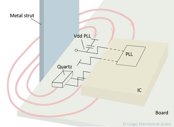
The metal strut to which the discharge is applied is adjacent to the microcontroller in the area of the PLL and quartz crystal oscillator circuits. The fault could not be demonstrated by applying the discharge to another metal strut. This gives rise to the suspicion that the ESD interferes with the quartz crystal oscillator or PLL circuit of the microcontroller (Figure 1). The ESD current generates a magnetic field vortex around the metal strut that penetrates the line networks of the quartz crystal oscillator and PLL circuits. This may result in two different faults.
- Quartz crystal oscillator circuits usually stop for a few 10 µs if a disturbance occurs. The quartz crystal oscillator may even stop for a millisecond in extreme cases. In our example, the disturbance is caused by the magnetic field which induces a voltage in the oscillator lines.
- The PLL power supply, i.e. Vss PLL and Vdd PLL, is the weak point in the PLL system. If disturbances occur, the PLL system usually locks in the maximum possible PLL frequency. This is higher than the microcontroller's permissible operating frequency and causes the microcontroller to crash.
The microcontroller crash is visualized by the life sign LED going out. The interference with the quartz crystal oscillator circuit usually causes the microcontroller to stop for just a few 10 µs. The microcontroller may also stop for several milliseconds in exceptional cases (crystal oscillator fault). The consequence of this fault is that all of the microcontroller's time-synchronous signal sequences, and in particular data transmission systems, USB or LAN networks become faulty. Simple UART systems are also affected by this fault. Due to the microcontroller stop, individual data bits are not transmitted. Such faults are remedied by correction procedures with USB or LAN. Data transmission is slowed down because of persistent fault correction / repetition with frequent disturbances. The transmission system link may be interrupted by severe interference. A USB is connected to the UART converter on the microcontroller in the example (Figure 1). A microcontroller stop due to quartz crystal oscillator interference will lead to UART system malfunctions which in turn may be transmitted to a PC and visualized. This enables an analysis of the effects caused by crystal oscillator faults. These data faults could be shown on the PC during an ESD test of the microcontroller board. This means that the quartz crystal oscillator of the microcontroller probably stops for just a few 100 µs when an ESD is applied. Corresponding fault registers can be read out in the microcontroller if the respective hardware, firmware and software are available. This data can be examined to determine whether quartz crystal oscillator or PLL faults occurred. If so, the initial considerations about the fault cause (quartz crystal oscillator and PLL fault) are confirmed. In any case, even if the fault registers cannot be read out, the microcontroller board has to be examined.
Fault analysis on the board
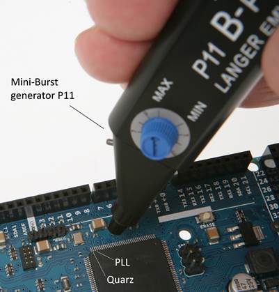
An appropriate specific fault analysis has to be carried out on the microcontroller board to confirm the initial suspicion of interference with the quartz crystal oscillator and PLL. A suitable tool for such an analysis are field sources that generate local fields with the required field intensity. These local fields must correspond to the fields that occur under the influence of ESD in practical use. A field source that generates a field beam with a diameter of approx. 4 mm was used in this example. The rise time of the pulse that is emitted by the field source is 1 ns, i.e. it is similar to a real ESD event. The field source must be able to induce pulse voltages of up to 20 V in conductor loops (Figure 2).
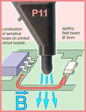
The field source is very small and flexible and is guided across the microcontroller by hand. The magnetic field is hereby coupled to the connected networks and pins as well as the housing of the microcontroller. All pins, line networks and housing areas are examined in the first step of the analysis. This rules out the occurrence of the fault pattern in other functional areas of the microcontroller. The field source is moved towards the quartz crystal oscillator and PLL circuits in the next step of the analysis. This results in an immediate crash at very low levels (Figure 4). The crash and the crystal oscillator faults are usually triggered stochastically when the field source is guided towards the lines. A closer examination revealed that the crash and the oscillator faults occurred when the field source was brought near the quartz crystal oscillator circuit. Only the crash fault occurred when the PLL circuit was approached. This confirms the initial suspicion of interference via the magnetic field that is generated during ESD. The sensitive line networks and pins can be pinpointed if the field source is guided with a great deal of technical skill.
In order to demonstrate the cause-and-effect relationships of the fault in the example, the metal strut was cut through and the ESD current applied in the strut area on the bottom of the microcontroller board. The ESD generator must be held horizontally to apply the ESD current to the strut so as to prevent the magnetic field that encircles the generator tip from interfering with the microcontroller. No magnetic field is generated on the top of the microcontroller board. The relationship is thus confirmed by the ESD generator test.
Cutting metal parts is not a feasible solution in practice. It simply confirms the initial suspicions. The developer cannot remedy the faults found in the test (line network, ground, additional filter elements) as the weak point is located in the microcontroller itself. The microcontroller with its pins forms the largest loops that take up the magnetic field. If a poor layout means that even larger loops exist on the board, its EMC immunity can be increased by improving the layout. The faults can also occur if the ground system under the PLL and quartz crystal oscillator is not continuous. The magnetic field may penetrate the PLL and quartz crystal oscillator lines through slots in the ground system. This does not happen however in our example. It could be shown that the disturbance current flowing through the metal strut and the resulting magnetic field as well as the induction loops formed by the IC pins were the cause in this case.
EMC measures to solve the problems
The following possible solutions can be derived for the practical field.
- Relocation of the IC on the microcontroller board to increase the distance from the PLL and crystal oscillator circuits to the metal strut.
- Modification of the mechanical design by moving the metal strut to a non-critical area.
- Use of a strut made of a non-conductive material (plastic strut).
- The plastic housing is shaped so that the metal strut is no longer accessible for the tip of the ESD generator.
- Shielding of the respective circuitry.
- Use of a suitably robust IC.
We recommend that the effect of the EMC measures that are taken be verified on a test sample. An immediate and completely new artwork design of the microcontroller board should be avoided. The existing board should be modified instead so that the effect of the aforementioned measures can be assessed.
Structural parts may affect quartz crystal oscillator and PLL circuits of a microcontroller in practical use.
- The housings of devices may contain metal struts in practice. The faults described here may occur under the influence of ESD on the housing if such a metal strut is arranged adjacent to the quartz crystal oscillator and PLL area of the microcontroller.
- An RJ45 connector used for LAN connections that is located on the microcontroller board may feed ESD current to the microcontroller board. The magnetic field that is thereby produced can cause the microcontroller's quartz crystal oscillator or PLL system to fail analogous to the example. The metallic isolation of the LAN system will not be helpful in this case as the magnetic field can enter the microcontroller across the isolating distance.
- Any other connectors such as USB, board-to-board connectors can cause these faults.
- Screws or bushings may be led through the microcontroller board.
- Angle brackets may be attached to the microcontroller board.
The developer must have EMC experience and practical skills in using field sources to suppress interference, eliminate faults and harden modules efficiently. A sound knowledge of EMC cause-and-effect relationships is also helpful. Attendance at a special EMC experimental seminar is worthwhile if EMV problems have to be solved frequently. Furthermore, an experienced EMC consultant can be asked for assistance in finding the cause of faults quickly and expediently in particularly difficult situations.